 EN
EN

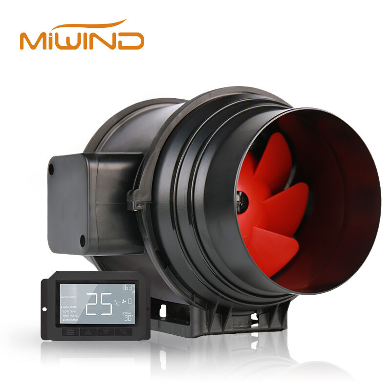
Integrating a duct fan into an existing or new HVAC layout is a decision that carries significant technical and operational weight. Whether you are designing a ventilation system for a commercial building, an industrial facility, or a residential complex, the placement, sizing, and coordination of each duct fan within the broader airflow network will determine whether the system performs efficiently or struggles with pressure imbalances, noise complaints, and energy waste. Getting these integration decisions right from the start saves considerable time, cost, and rework down the line.
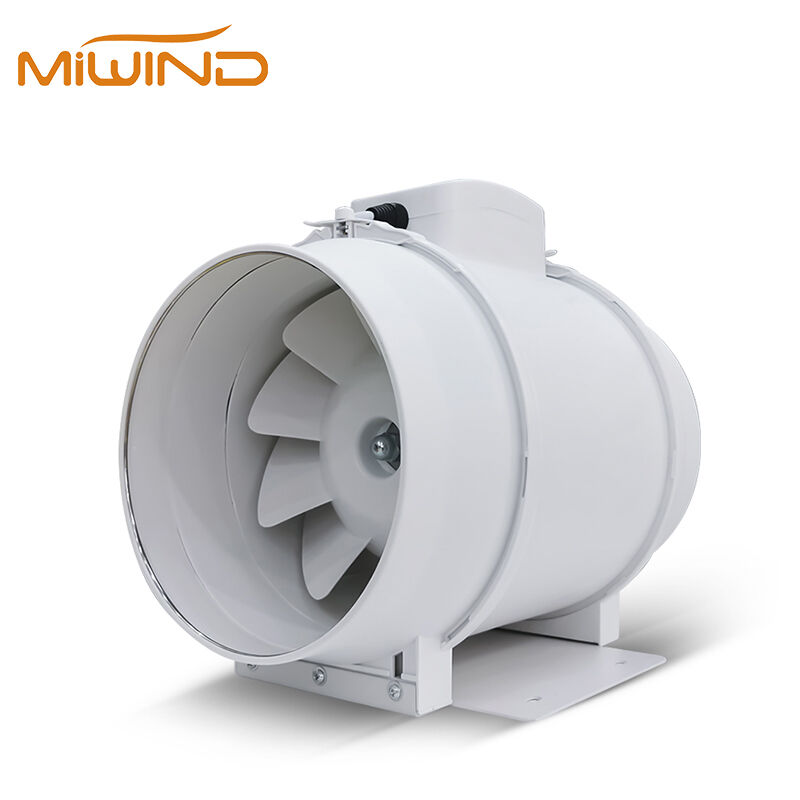
The process of incorporating a duct fan into an HVAC layout is not simply a matter of selecting a unit and inserting it into a duct run. It requires a structured evaluation of airflow requirements, duct geometry, static pressure conditions, control compatibility, and long-term maintenance access. Each of these factors interacts with the others, meaning that a misstep in one area can cascade into problems across the entire system. This article walks through the key considerations that engineers, contractors, and facility managers should address when planning duct fan integration.
Understanding Airflow Requirements Before Selecting a Duct Fan
Calculating the Required Air Volume
Before any duct fan is specified, the design team must establish the total air volume the system needs to move, typically expressed in cubic feet per minute or cubic meters per hour. This figure is derived from the occupancy load, the thermal demands of the space, and any ventilation codes that apply to the building type. Underestimating this value leads to a duct fan that is perpetually running at maximum capacity, shortening its service life and failing to meet comfort or air quality targets.
Overestimating the required air volume is equally problematic. An oversized duct fan introduces excessive velocity pressure into the duct network, which can cause turbulence, noise amplification, and uneven distribution across branch runs. The goal is to match the duct fan capacity as closely as possible to the verified demand, with a modest safety margin rather than a generous oversize.
It is also worth accounting for future load changes. If the space is likely to be reconfigured or expanded, selecting a duct fan with variable speed capability allows the system to adapt without requiring a full unit replacement. This forward-looking approach is particularly relevant in commercial and light industrial settings where tenant needs evolve over time.
Mapping Pressure Losses Across the Duct Network
Every element in a duct system — fittings, dampers, filters, coils, and duct length — contributes to the total static pressure that the duct fan must overcome. A thorough pressure loss calculation, often called a system curve analysis, is essential before finalizing the duct fan selection. If the total external static pressure is underestimated, the chosen duct fan will not deliver the intended airflow, regardless of its rated capacity.
The system curve must account for the worst-case path through the duct network, which is typically the longest or most restricted branch. This index circuit defines the minimum pressure the duct fan must generate to serve all zones adequately. Designers who skip this step often find themselves adding supplemental fans or reworking duct sections after installation, both of which are costly and disruptive.
When multiple duct fan units are planned for a single system, the interaction between their individual pressure contributions must also be modeled. Fans operating in series increase static pressure capacity, while fans in parallel increase volume flow. Understanding which configuration suits the layout prevents conflicts where one duct fan inadvertently works against another.
Duct Geometry and Physical Integration Factors
Straight Duct Length Requirements Around the Fan
A duct fan performs best when it receives a uniform, undisturbed airflow profile at its inlet. This means the duct section immediately upstream of the fan should be straight and free of elbows, transitions, or obstructions for a minimum distance — typically several duct diameters, as specified by the manufacturer. Violating this requirement creates turbulent inlet conditions that reduce the duct fan efficiency and increase noise generation.
The outlet side of the duct fan also benefits from a straight duct run before any fitting or branch takeoff. Abrupt direction changes immediately downstream of the fan force the motor to work harder against the resulting pressure recovery losses. In tight mechanical rooms or ceiling plenum installations where straight runs are difficult to achieve, the designer may need to select a duct fan model specifically rated for restricted inlet and outlet conditions.
Flexible duct connections are sometimes used at the duct fan inlet and outlet to reduce vibration transmission into the rigid duct network. While this is a sound practice for noise control, the flexible sections must be kept short and fully extended. Compressed or kinked flexible connectors act as significant flow restrictions and can negate the performance gains the duct fan was installed to provide.
Duct Size Matching and Transition Design
The duct fan housing diameter must match the duct diameter at the point of installation, or a properly designed transition must be used. Abrupt area changes at the fan connection create velocity pressure losses and flow separation that reduce the effective output of the duct fan. Gradual transitions with expansion angles no greater than fifteen degrees on each side are the standard recommendation for minimizing these losses.
In retrofit projects, the existing duct size may not align with the available duct fan models. In these cases, the designer must evaluate whether resizing a section of duct is more cost-effective than accepting the performance penalty of a mismatched connection. For short duct runs or low-velocity systems, the impact may be acceptable. For high-volume or high-pressure applications, the mismatch can be a significant source of inefficiency.
Round duct connections are generally preferred for duct fan installations because they provide a uniform velocity profile across the fan blade sweep. Rectangular-to-round transitions upstream of the duct fan should be designed carefully to avoid dead zones in the corners of the rectangular section, which contribute to uneven loading on the fan impeller.
Control System Compatibility and Integration Logic
Matching the Duct Fan to the Building Automation System
Modern HVAC layouts are increasingly managed by building automation systems that coordinate temperature, humidity, occupancy, and air quality data to optimize energy use. A duct fan that cannot communicate with the building automation system operates as an isolated component, unable to respond to system-wide commands or contribute to demand-controlled ventilation strategies. Before specifying a duct fan, the design team should confirm that its control interface — whether analog, digital, or protocol-based — is compatible with the existing or planned automation platform.
Variable frequency drives are a common method for integrating duct fan speed control into a building automation system. The drive receives a signal from the automation controller and adjusts the fan motor speed accordingly, allowing the duct fan to modulate airflow in response to real-time demand rather than running at a fixed speed. This approach delivers meaningful energy savings in systems where the ventilation load varies significantly throughout the day.
For simpler installations, a duct fan may be controlled by a local thermostat, a humidity sensor, or a manual switch. Even in these cases, the control wiring and switching logic should be documented clearly in the system design so that future maintenance personnel understand how the duct fan is intended to operate and can troubleshoot it without guesswork.
Interlock and Safety Control Considerations
A duct fan should not operate in isolation from the rest of the HVAC system. Interlocks that prevent the duct fan from running when associated air handling units, dampers, or exhaust systems are offline are essential for maintaining safe and balanced airflow conditions. Without these interlocks, a duct fan can create negative pressure zones that draw in unconditioned air, backdraft combustion appliances, or cause doors and dampers to behave unexpectedly.
Fire and smoke control requirements must also be addressed during the integration design. In many jurisdictions, duct fans installed in smoke control zones must be capable of being shut down automatically upon activation of the fire alarm system. The duct fan specification should confirm that the motor and controls are compatible with the fire alarm interface, and the installation must be coordinated with the fire protection engineer.
Thermal overload protection is a standard feature on most duct fan motors, but the designer should verify that the protection settings are appropriate for the installation environment. A duct fan installed in a high-temperature exhaust application, for example, requires a motor rated for elevated ambient temperatures, and the overload protection must be calibrated accordingly to avoid nuisance trips.
Noise, Vibration, and Structural Mounting Considerations
Selecting Mounting Configurations That Minimize Vibration Transfer
A duct fan generates mechanical vibration during operation, and if this vibration is transmitted directly into the building structure or duct network, it becomes an audible noise problem for occupants. Anti-vibration mounts — rubber isolators, spring hangers, or inertia bases — are used to decouple the duct fan from its support structure and reduce the transmission of vibration energy. The appropriate isolator type depends on the fan weight, operating speed, and the sensitivity of the surrounding spaces.
In ceiling-mounted installations, the duct fan is typically suspended from structural members using threaded rod hangers with rubber grommets or spring isolators at the attachment points. The hanger spacing and rod diameter must be sufficient to support the fan weight without deflection, and the isolators must be selected for the correct load range to function effectively. An isolator that is overloaded or underloaded provides little vibration attenuation.
The duct connections at the duct fan inlet and outlet should incorporate flexible sections, as mentioned earlier, to prevent vibration from traveling along the rigid duct network. These flexible connectors should be made from materials compatible with the airstream temperature and any contaminants present, and they should be inspected periodically for deterioration.
Acoustic Performance and Duct Attenuation
Beyond mechanical vibration, a duct fan generates aerodynamic noise that propagates through the duct system and radiates into occupied spaces. The sound power level of the duct fan, expressed in decibels across octave bands, should be obtained from the manufacturer and used to calculate the expected sound pressure level at the nearest occupied space. If the predicted level exceeds the design criterion, duct silencers or acoustic lining must be incorporated into the duct runs upstream and downstream of the duct fan.
The duct routing itself can either amplify or attenuate fan noise. Long, straight duct runs with acoustically lined walls provide natural attenuation, while short, unlined runs deliver fan noise directly to diffusers and grilles. In noise-sensitive applications such as offices, classrooms, or healthcare facilities, the acoustic design of the duct system around the duct fan deserves as much attention as the hydraulic design.
Operating the duct fan at reduced speed through variable frequency drive control is one of the most effective ways to reduce noise output. Fan noise increases sharply with speed — roughly as the fifth power of the velocity ratio — so even a modest reduction in operating speed can produce a significant drop in sound level. This is another reason why variable speed capability is a valuable feature when integrating a duct fan into noise-sensitive HVAC layouts.
Maintenance Access and Long-Term Serviceability
Providing Adequate Access for Inspection and Cleaning
A duct fan that cannot be easily accessed for inspection, cleaning, and component replacement will be neglected, and a neglected duct fan will eventually fail or perform below its rated capacity. During the layout design phase, the engineer should confirm that the duct fan location allows a technician to reach the unit with appropriate tools and to remove the fan assembly if necessary for motor or impeller service.
Access panels in the duct system adjacent to the duct fan are a minimum requirement. In ceiling plenum installations, the access panel must be large enough to allow the fan housing to be lowered through it if the unit needs to be removed. Designing the installation without this consideration often results in technicians cutting new openings in finished ceilings during the first major service event, which is both costly and disruptive.
The duct fan should also be positioned so that the electrical connections and control wiring are accessible without requiring the fan to be removed. Labeling the wiring clearly and providing a local disconnect switch within sight of the duct fan are practices that simplify both routine maintenance and emergency response.
Establishing a Preventive Maintenance Schedule
Like all rotating equipment, a duct fan requires periodic maintenance to sustain its performance and extend its service life. The maintenance schedule should be established at the time of installation and incorporated into the building's overall maintenance program. Key tasks typically include inspecting and cleaning the impeller, checking motor bearings for wear or overheating, verifying that flexible duct connectors are intact, and confirming that the control system is responding correctly to demand signals.
The frequency of maintenance depends on the operating environment. A duct fan handling clean supply air in a commercial office building may require only annual inspection, while a duct fan in a kitchen exhaust or industrial process ventilation application may need quarterly cleaning to prevent grease or particulate buildup on the impeller blades. Buildup on the impeller changes its aerodynamic profile, reduces airflow, and increases motor current draw, all of which shorten the duct fan service life.
Keeping maintenance records for each duct fan in the system allows facility managers to identify units that are consuming more energy or requiring more frequent attention than expected. These patterns often indicate an underlying issue — such as a misaligned duct connection, a deteriorating bearing, or a control system fault — that can be corrected before it leads to a complete failure.
FAQ
Where in the duct system should a duct fan be installed for best performance?
A duct fan performs best when installed in a straight section of duct with several duct diameters of unobstructed run on both the inlet and outlet sides. Avoid placing the duct fan immediately after elbows, transitions, or branch takeoffs, as these create turbulent inlet conditions that reduce efficiency and increase noise. In practice, the exact location should be determined by the pressure loss analysis and the physical constraints of the building layout, with the goal of minimizing inlet disturbance while keeping the unit accessible for maintenance.
Can a single duct fan serve multiple zones in an HVAC layout?
A single duct fan can serve multiple zones if it is installed in the main duct trunk before the branch takeoffs and if its capacity is sized to meet the combined demand of all zones it serves. However, balancing airflow across multiple branches requires careful duct design and, in many cases, balancing dampers in each branch. If the zones have significantly different load profiles or operating schedules, individual duct fan units per zone — or a variable speed unit with zone damper control — may provide better performance and energy efficiency than a single shared unit.
What is the impact of duct leakage on duct fan performance?
Duct leakage is one of the most common causes of duct fan underperformance. When conditioned air escapes through unsealed joints, seams, or penetrations before reaching the intended supply outlets, the duct fan must work harder to compensate, often running at higher speeds and consuming more energy without delivering the expected airflow to occupied spaces. Sealing the duct system to the appropriate leakage class before commissioning the duct fan is essential for achieving the design performance. In retrofit projects, duct leakage testing and sealing should be completed before the new duct fan is installed.
How does ambient temperature affect duct fan selection for exhaust applications?
In exhaust applications where the duct fan handles elevated-temperature air — such as kitchen exhaust, industrial process ventilation, or heat recovery systems — the motor and impeller materials must be rated for the maximum expected airstream temperature. Standard duct fan motors are typically rated for ambient temperatures up to forty degrees Celsius. Applications with higher airstream temperatures require motors with Class F or Class H insulation, high-temperature bearings, and impeller materials that maintain their structural integrity under thermal stress. Selecting a duct fan without verifying its temperature rating for the specific application is a common and costly oversight.